Electronics
Production
This
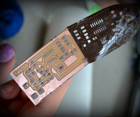
week's assignment was to mill, solder, and program a FabISP circuit board.
The FabISP is an in system programmer for AVR
microcontrollers, specifically designed for fab labs. It uses a USB cable and a
6 pin IDC to 6 pin IDC cable to communicate. With this, the ATTiny
can communicate with Serial Software. Our first step was to use Eagle, a free
program you can use to design your own circuit board. It stands for Easily
Applicable Graphical Layout Editor. It can be a bit tricky for beginners. There
are lots of icons to explore. The first thing we did in Eagle was to download
the fab libraries so we could find the right components. Fist
you lay out a schematic, and then you move on to the board design. There are
many ways to route your board. I used the auto router a few times to see what
it would come up with. Then it was time to mill the boards!
After
a few adjustments, we learned how to prep the FR4 board. The FR4 stands for a
mix of epoxy, resin, and fiberglass. The "RF4" stands for flame
retardant. We used doubled sided tape to secure FR4 board to the medium-density
fibreboard, which was also taped down to milling
surface. This MDF wood would allow us to cut all the way through the FR4 board,
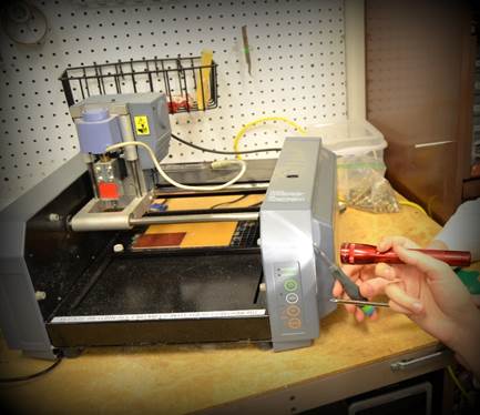
and not damage the Modela's plate. We also learned
how to change the drill bit. It is important to keep pressure on the bit while
tightening, so that it stays in place. Over tightening can cause the bit to
shift. Pressing the view button allowed us to get the drill into place. 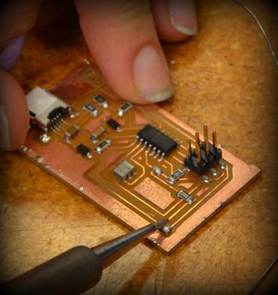 We
then sent the rml file to the modela
and watched the drilling process.
We
then sent the rml file to the modela
and watched the drilling process.
It
is best to have a mini vacuum to keep milling surface free of shavings. A can
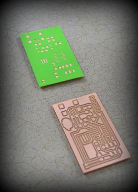
of air will also suffice. Once the board was milled, we cleaned it, and placed
a vinyl sticker stencil we made using the Silhouette. Clear contact paper
allowed us to place the sticker over the tiny rectangles of the board
accurately. It helps to double side tape the board down when placing the
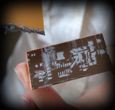
stencil. Solder paste was then scraped onto the board evenly. When peeling off
the sticker, it is best to pull gently and slowly. Placing the electrical
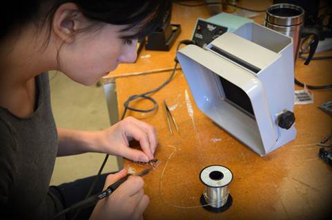
components is tricky. We placed the microcontroller first, so that pin 1 was
lined up. It takes a steady hand and a good pair of tweezers. We saved the
headers for last. Then we baked it in the 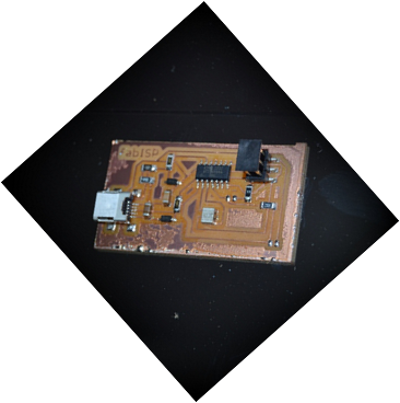 oven!
It took about 2 minutes at 475 degrees for the all of the solder to turn shiny.
Once it did, we carefully removed the board and let cool before checking it
over.
oven!
It took about 2 minutes at 475 degrees for the all of the solder to turn shiny.
Once it did, we carefully removed the board and let cool before checking it
over.
I enjoyed placing the components, so I placed the
parts for a second circuit board, and baked that one too. They both turned out
successful! Then we had to solder the jumpers before programming. When
programming went well, we desoldered the jumpers so
that the newly programmed circuit board could be used to program the next one.
Making the cables was the easiest part.